
Top-Down Method: A Geotechnical Advantage for Urban Development
What Is the Top-Down Method?
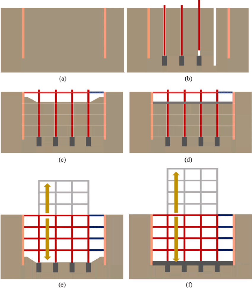
In typical construction projects, excavation is performed first, followed by foundation work and then the superstructure. Top-Down is a modern excavation‑support method that has become increasingly common in Iran in recent years. In this method, the construction of the substructure and superstructure occurs simultaneously, which is why it is referred to as the “top-down construction technique.”
Top-down construction around the world usually begins with building the perimeter walls, which may consist of diaphragm walls, sheet piles, secant piles, or similar systems. Diaphragm walls are commonly constructed using hydromills or grabs.In large cities such as Tehran—where the soil is generally stiff, the groundwater level is low, and the available construction space is limited—this method is often not cost‑effective, except in special circumstances.
In the localized (Iranian) version of the Top-Down method, the natural stability of the soil between the columns is utilized during each stage of excavation before the permanent retaining walls are installed. When the soil is weak or the spacing between columns is large, temporary measures such as additional intermediate columns, mesh reinforcement, or shotcrete can be used to increase stability.
Top-Down Construction Steps
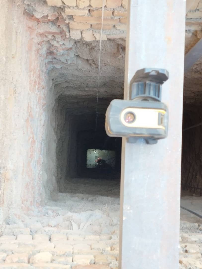
1. Shaft Excavation
After leveling the site, the exact positions of all columns are marked. For constructing the perimeter columns in the Top-Down method, vertical shafts must be excavated at the column locations.
The depth of each shaft equals the total column length plus the required pile length. Shaft dimensions are based on the size of the column, base plate, and pile design requirements. The shaft must be large enough for the column and base plate to be lowered and positioned without obstruction.
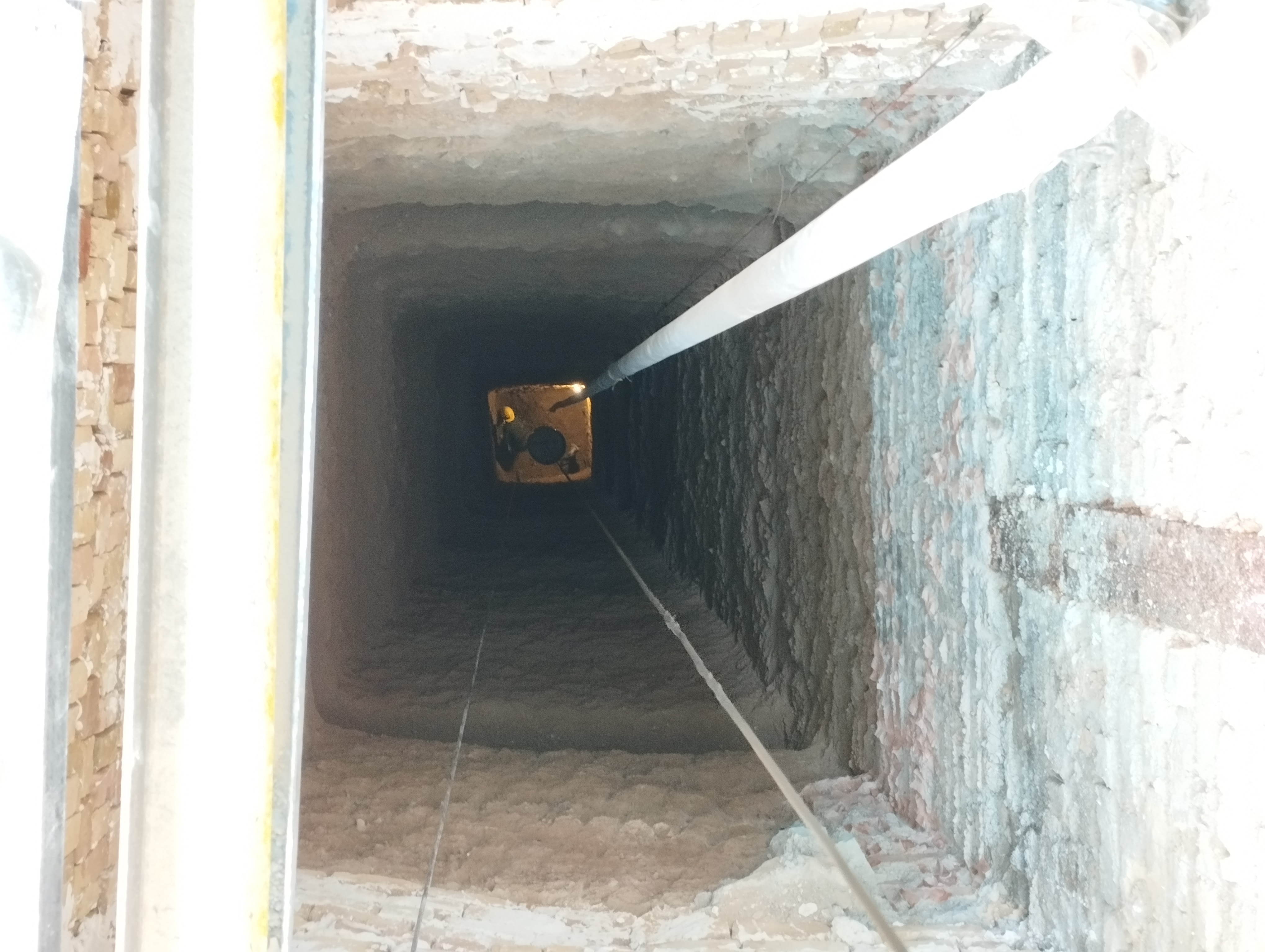
In cities such as Tehran, where the soil is relatively stiff and suitable for excavation, these shafts are generally dug manually. Manual excavation offers several advantages:
• It allows the shaft to be excavated in various geometric cross‑sections.
• Loose soil in the shaft walls can be removed during excavation, and the resulting surface roughness increases the interlock between concrete and soil, thereby improving the pile’s load‑bearing capacity.
• Verticality can be carefully controlled and ensured throughout all stages of excavation.
Despite these advantages, manual shaft excavation also has some drawbacks:
• Low safety for workers
• Low execution speed
The second issue can be addressed by using multiple excavation crews simultaneously to increase productivity.
In the Top‑Down method, additional reinforcing columns may be added to the perimeter columns to resist the compressive forces exerted by the soil. Excavation of appropriately sized and deep shafts is also required for installing these reinforcing members.
2. Horizontal Gallery Excavation
After the shafts are excavated, horizontal galleries must be created at the shallow foundation level to provide better and safer access between the shafts. These galleries are temporary and will be removed before the shallow foundation is constructed.
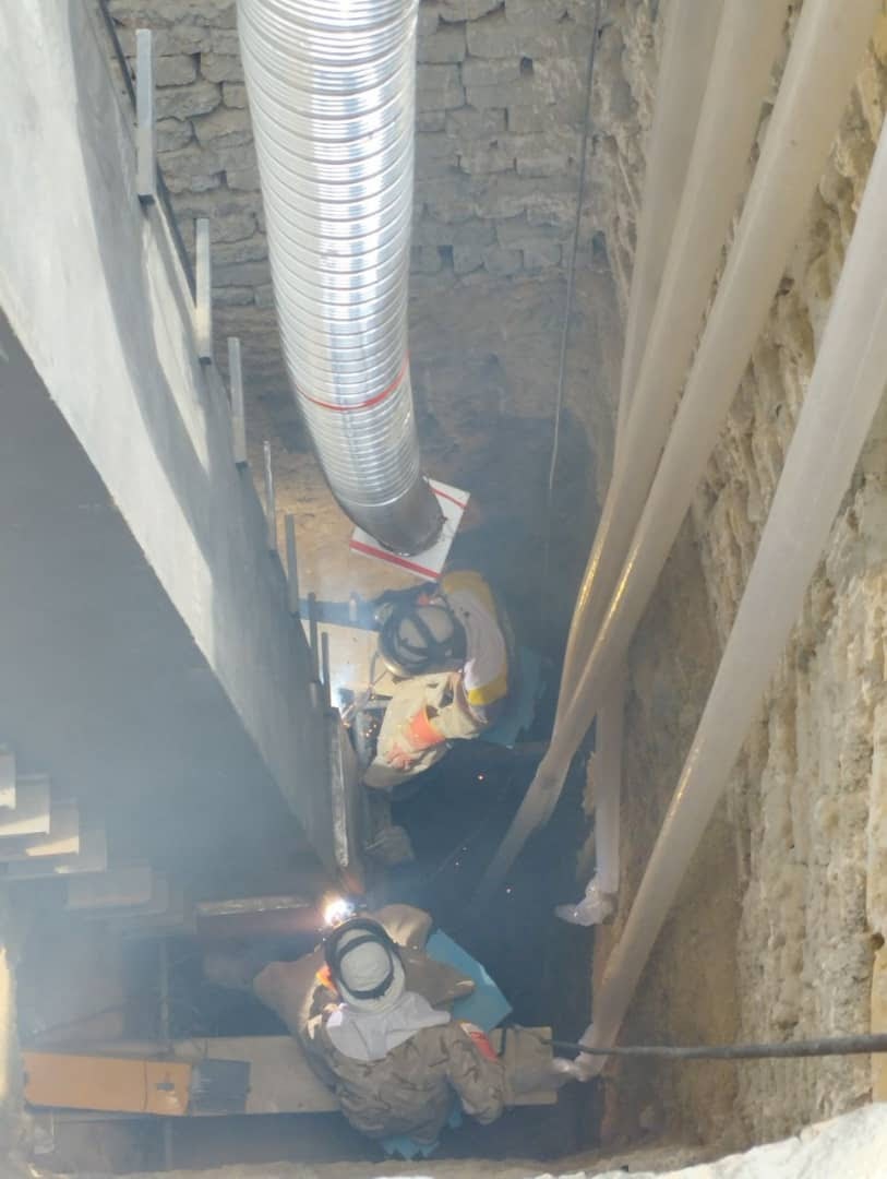
3. Pile and Column Construction
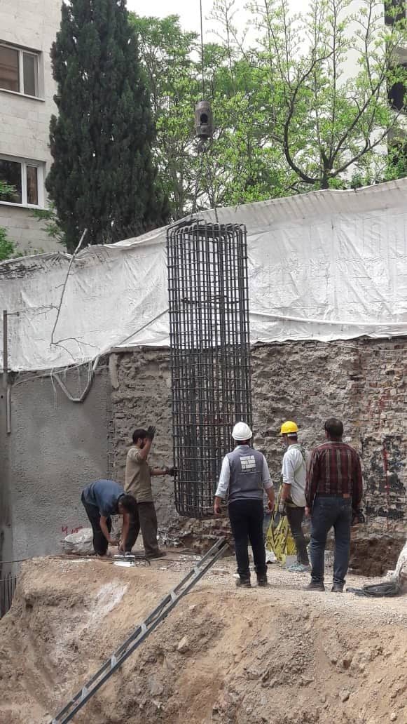
Rebar Cage Fabrication and Placement
At this stage, rebar cages for the piles are fabricated. This process is carried out in parallel with shaft excavation. After the shafts are completed, the rebar cages must be lowered into the shafts. To ensure the minimum required concrete cover, spacers can be used. Additionally, the upper rebar hooks should not be bent inward toward the center of the cage, as this may interfere with the placement of the steel column.
When the crane lifts the rebar cage, it may deform under its own weight. During placement, the cage may also strike the shaft walls, which could cause soil chunks to fall. To mitigate this issue, the shaft depth is typically excavated about 20 centimeters deeper than required.
4. Connection of the Column to the Pile
After placing the reinforcement cage, the next step is positioning the column and connecting it to the pile. Depending on the type of column, the following connection methods are used:
5. Steel Column
1. Embedding Part of the Column Length
In this method, a portion of the steel column is embedded inside the pile. To reduce the required embedment length, shear connectors such as channels or studs are typically used.
In this method, the rebar hooks at the top of the pile should not be bent toward the center of the pile so that the column can be inserted easily into the reinforcement cage.
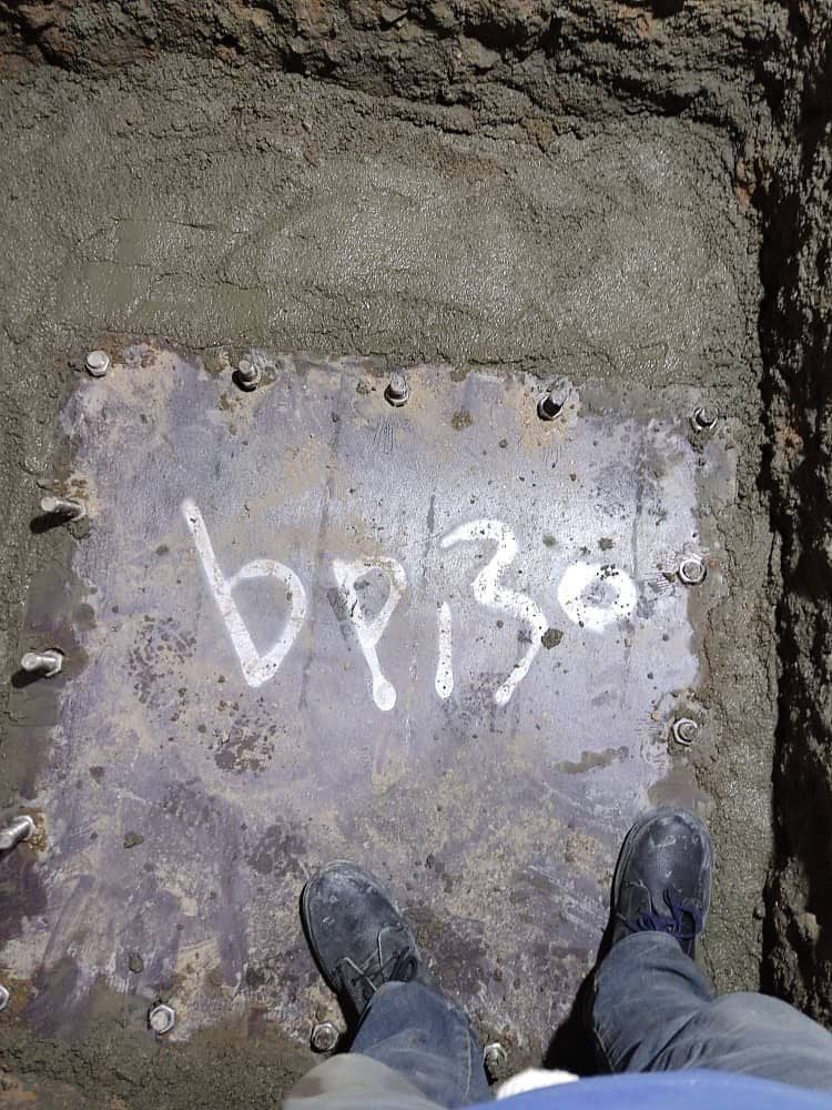
2. Connecting the Pile to the Column Using a Base Plate
In this method, the position of the columns is first established using surveying equipment. Then, a temporary collar beam (capping beam) is constructed at the top of the shaft.
After marking the column centerlines and constructing the collar beam, the centerline is transferred from the ground surface to the pile head using a plumb line or laser level. A template (shablon) is then placed on the pile according to the column location and fixed in position.
Next, concrete and grout are placed up to the underside of the template. After that, the exact location of the column is marked on the template, the template is removed, and finally, the column and base plate are installed.
In Top-Down construction using a reinforced‑concrete frame, precast concrete columns are typically used. These columns are connected to the pile using one of the following methods:
The bottom of the precast column is manufactured with a steel section, and the column is connected to the pile using a steel component and tension rods (anchor bars).
A series of couplers are embedded at the bottom of the precast column, and the dowel bars extending from the pile are connected to the column using mechanical splices.
7. Backfilling Around the Column
After constructing the pile and placing the column, the empty space surrounding the column must be filled with a proper mixture of soil and cement so the column remains stable and fixed within the ground.
The strength of this mixture must be sufficient to support the column, but if it is too strong, it may cause difficulties during excavation and subsequent construction stages.
8. Excavation
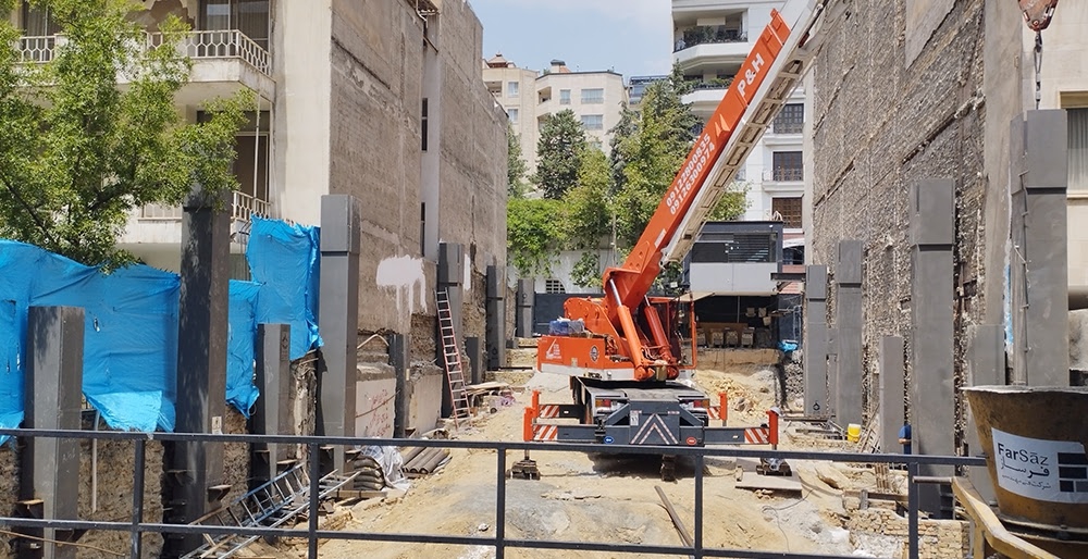
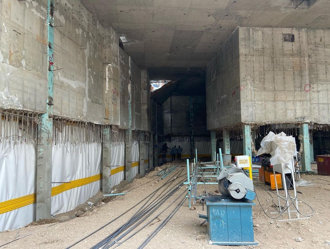
Once the previous steps are completed, excavation proceeds down to the first basement level. Excavation is one of the most challenging stages of the Top-Down method and requires close coordination between the excavation team and the structural construction team.
At the beginning, proper excavation equipment must be selected based on the site dimensions and project scale, and an appropriate excavation pattern must be defined.
Openings for the entry and exit of construction machinery, material handling, and the movement of workers must also be identified.
Since the basement levels typically have low floor heights (usually less than 3 meters), conventional excavation machinery cannot be used, and smaller machines must be selected.
If project conditions require larger equipment, feasibility must be checked during the design phase.
After completing the first stage of excavation, temporary stabilization of the excavation walls must be carried out to prevent localized soil collapse.
9. Waterproofing and Drainage
If the groundwater level is high and proper measures are not taken, significant challenges may arise during construction and the long-term performance of the structure.
Therefore, in the Top-Down method, a suitable system must be designed for waterproofing and managing groundwater flow. To waterproof the excavation walls, materials such as geotextiles and geomembranes are commonly used.
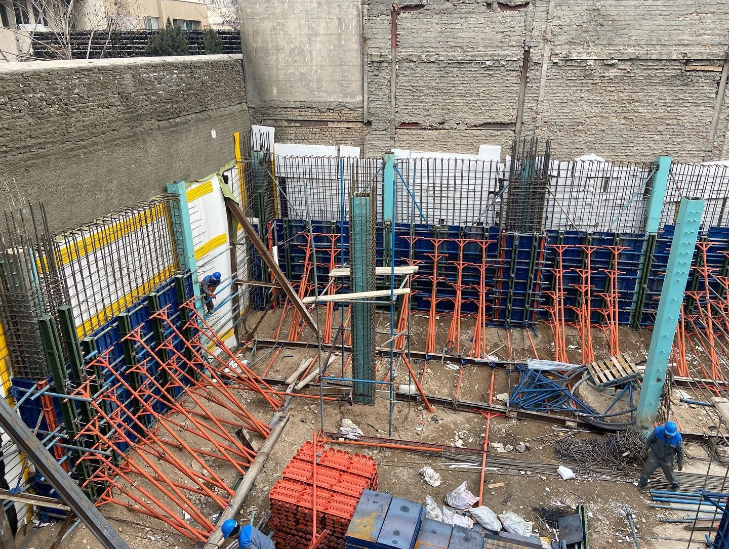
In the Iranian adaptation of the Top-Down method, efforts are made to take advantage of the natural bearing capacity of the soil before constructing the permanent retaining walls. To do this, excavation is carried out in a staggered (toothed) pattern, so that the soil itself contributes to temporary stability at the required excavation level.
After these steps, the retaining wall can be cast in-place using single-sided formwork.
These walls are connected to the steel columns by shear studs or headed studs, and to concrete columns using couplers embedded in the column.
Connection of the retaining walls to the slabs, adjacent walls, and the foundation is performed using one of the following four methods:
- Mechanical couplers
- Welded splice
- Lap splice
- Rebar anchorage (rebar dowelling)
In regions with soft soil and high groundwater levels, continuous perimeter walls are used. These walls are usually constructed using hydrofraise cutters or clamshell grabs.
Other methods that can be used to construct continuous perimeter retaining walls include:
• Secant piles
• Contiguous piles
• Steel sheet piles
• Jet-grouting columns
11. Slab Construction
After excavation and completing the steps described above, the floor slab of the level can be constructed.
There is no specific restriction on the choice of slab system in the Top-Down (reverse construction) method; however, it is preferable not to use systems requiring beams or extensive shoring, as such systems are not optimal for Top-Down execution.
12. Repetition of Excavation, Wall Construction, and Slab Construction Until Reaching the Foundation Level
After completing the first basement level, excavation continues to the next slab level. The previously described stages are repeated until the foundation (sub‑foundation) level is reached.
Advantages of the Top-Down Method
• Simultaneous construction of superstructure and substructure
• Time and cost savings compared to some other excavation support methods
• Suitable for basement construction in areas with high groundwater level
• Applicable in underpasses, underground spaces, and tanks
• Reduced dust generation and fewer environmental issues
• Minimizes traffic disruption and equipment‑related congestion
• Better control of soil movements and prevention of instability during excavation
• No need for neighboring property consent
• Optimized structural design due to integration of superstructure and substructure elements (e.g., retaining wall and shear wall, pile and column)
• Use of shaft friction to improve load-bearing capacity and settlement performance
• Wide applicability in buildings with multiple basement levels
• Box‑type behavior of the system enhances foundation performance
Disadvantages of the Top-Down Method
• Excavation cannot be carried out continuously
• Access to the excavation is limited to shafts and openings
• Small floor heights in basements require specialized compact machinery
• Requires highly specialized Top‑Down construction crews
• Ventilation significantly affects construction quality
• Complex detailing for slab‑to‑column and slab‑to‑wall connections
• Lower construction speed for the substructure